STEREO/Waves antenna Quick Facts
Spacecraft Frame
The pointing direction of an antenna is given by 2 angles. These angles are given in the spacecraft frame. However, there are several ways to define these angles. The following figure shows the two spherical coordinate systems that can be used with the STEREO/Waves antennas:
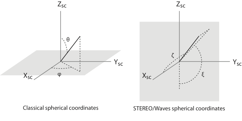
On the left hand panel, θ and φ are the classical colatitude and azimuths. On the right hand panel, ζ is the "colatitude from the +X axis" and ξ the "azimuth from the -Z axis". This latter spherical coordinate system is specific to STEREO/Waves and has been introduced by Bale at al. [2008].
Physical Parameters
The physical parameter of the electrical antennas (for STEREO A and B spacecraft) are:
| Antenna | Length (m) | θ (deg) | φ (deg) | ζ (deg) | ξ (deg) |
|---|---|---|---|---|---|
| hX | 6.000 | 65.90 | 230.77 | 125.16 | -120.00 |
| hY | 6.000 | 65.90 | 129.23 | 125.16 | 120.00 |
| hZ | 6.000 | 144.74 | 180.00 | 125.16 | 0.00 |
| hXY | 8.485 | 90.00 | 90.00 | 90.00 | 90.00 |
| hYZ | 8.485 | 150.00 | -90.00 | 90.00 | -30.00 |
| hZX | 8.485 | 30.00 | -90.00 | 90.00 | -150.00 |
Calibration Techniques
The spacecraft body and the antenna fixation device is modifying the gain the effective direction of the electrical antennas. The effective antenna parameters can be seen as the antenna parameters of a perfect dipole having the same response to input signals. The antennas can be calibrated by three methods. The citation provided in this section are also referring to the Cassini/RPWS electrical antenna calibration studies, as they can help understanding the various methods.
- Rheometric Analysis: A scaled model of the spacecraft is place into a conductive medium, and the antenna response is directly measured at the antenna feeds [Rucker et al., 1996, Macher et al., 2007]. A study by Macher and Oswald [2011] discusses the limitations of the rheometric analysis and proposes an analytical correction for the effective length determination.
- Wire-Grid Modeling: The spacecraft is modeled as a set a conductive elements and the antenna response is obtained using various electromagnetic modeling softwares. The two modeling software used here are:
- ASAP (Antenna Scatterers Analysis Program): this code was originally written by JW McCormack on the basis of a code developed by JH Richmond (Ohio State University);
- CONCEPT (COde for the Numerical Computation of Electromagnetic Processes for thin wire and thin shell structures): this code is a program developed at the Department of Theoretical Electrical Engineering of the Technical University Hamburg-Harburg.
- In-flight Calibration: A known radio-source is used as a calibrator after the antenna are deployed in space [Vogl et al., 2004, Cecconi et al., 2005].
Note that the antenna length provided in following tables should be compared with the "Γ.Leff" effective length presented in the Antenna length page, except when relative lengths are given.
Calibrated Parameters
Rheometric analysis and wire-grid modeling can be conducted with or without loading the antenna feeds on an impedance (acting as a fake radio receiver). We present here various published (and not published) calibrations:
- [Oswald et al., 2006]. Wire-Grid modeling using the ASAP software tool. Only the monopole antennas were calibrated.
- STEREO-A, Loaded feeds:
Antenna Length (m) θ (deg) φ (deg) ζ (deg) ξ (deg) hX 0.99 52.28 225.75 123.50 -137.20 hY 1.21 58.62 122.25 117.10 125.80 hZ 0.83 139.29 161.85 128.30 15.00 - STEREO-B, Loaded feeds:
Antenna Length (m) θ (deg) φ (deg) ζ (deg) ξ (deg) hX 0.98 53.48 226.91 123.30 -135.40 hY 1.18 59.22 122.39 117.40 125.20 hZ 0.84 140.82 163.14 127.20 13.30
- STEREO-A, Loaded feeds:
- [Macher et al., 2007]. Wire-Grid modeling using the ASAP software tool. Calibration parameters applicable to either STEREO-A or STEREO-B. Only the monopole antennas were calibrated.
- Open feeds:
Antenna Length (m) θ (deg) φ (deg) ζ (deg) ξ (deg) hX 3.05 52.53 220.74 125.80 -141.60 hY 3.85 56.37 125.35 118.80 129.20 hZ 2.32 132.32 158.87 133.60 21.60 - Loaded feeds:
Antenna Length (m) θ (deg) φ (deg) ζ (deg) ξ (deg) hX 1.18 52.07 230.95 119.80 -135.10 hY 1.43 56.39 119.61 114.30 127.40 hZ 0.96 142.77 159.05 124.40 15.20
- Open feeds:
- [Bale et al., 2008]. Various calibration methods performed by the Berkeley and the Graz teams. Calibration parameters applicable to either STEREO-A or STEREO-B. Only the monopole antennas were calibrated.
- Rheometric calibration performed by the Berkeley team, open feeds:
Antenna Length (m) θ (deg) φ (deg) ζ (deg) ξ (deg) hX 3.04 47.37 215.12 127.00 -148.00 hY 3.95 61.62 125.59 120.80 123.60 hZ 2.45 132.81 157.32 132.60 22.60 - Mean value for various calibrations performed by the Graz team, open feeds:
Antenna Length (m) θ (deg) φ (deg) ζ (deg) ξ (deg) hX 2.98 50.91 220.78 126.00 -141.20 hY 3.85 56.78 125.16 118.80 128.70 hZ 2.24 132.88 158.54 133.00 21.50 - Mean value for various calibrations performed by the Graz team, loaded feeds:
Antenna Length (m) θ (deg) φ (deg) ζ (deg) ξ (deg) hX 1.17 52.33 230.54 120.20 -135.00 hY 1.44 56.71 119.74 114.50 127.10 hZ 0.97 142.58 158.75 124.50 15.50
- Rheometric calibration performed by the Berkeley team, open feeds:
- [Oswald et al., 2009]. Wire-Grid modeling using the ASAP or CONCEPT software tools, as well as rheometry. Calibration parameters computed for STEREO-A. Only the monopole antennas were calibrated.
- ASAP, open feeds:
Antenna Length (m) θ (deg) φ (deg) ζ (deg) ξ (deg) hX 3.03 50.78 220.65 126.00 -141.10 hY 3.82 56.56 125.65 119.10 129.10 hZ 2.31 132.31 159.10 133.70 21.40 - ASAP, loaded feeds:
Antenna Length (m) θ (deg) φ (deg) ζ (deg) ξ (deg) hX 1.36 51.71 230.14 120.20 -135.80 hY 1.66 56.58 120.67 115.20 127.50 hZ 1.10 141.35 159.13 125.70 15.90 - CONCEPT, open feeds:
Antenna Length (m) θ (deg) φ (deg) ζ (deg) ξ (deg) hX 3.02 50.49 221.34 125.40 -141.30 hY 3.81 56.46 125.05 118.60 129.00 hZ 2.30 132.66 158.83 133.30 21.40 - CONCEPT, loaded feeds:
Antenna Length (m) θ (deg) φ (deg) ζ (deg) ξ (deg) hX 1.35 51.96 230.73 119.90 -135.30 hY 1.66 56.51 119.69 114.40 127.30 hZ 1.09 142.40 158.90 124.70 15.50 - Rheometry, open feeds:
Antenna Length (m) θ (deg) φ (deg) ζ (deg) ξ (deg) hX 2.89 51.36 220.87 126.20 -140.70 hY 3.84 57.40 124.75 118.70 127.90 hZ 2.36 133.53 157.90 132.20 21.60 - Rheometry, loaded feeds:
Antenna Length (m) θ (deg) φ (deg) ζ (deg) ξ (deg) hX 1.34 52.53 229.11 121.30 -135.40 hY 1.69 57.15 120.33 115.10 126.80 hZ 1.13 141.53 158.26 125.30 16.40
- ASAP, open feeds:
- Inflight calibration has been done using AKR sources by M. Panchenko. This calibration is not published yet. The inflight calibration were performed with STEREO-B data, for monopole and dipoles antenna configurations. Please contact M. Panchenko before using these numbers. The inflight calibration has been performed with data from 3 antenna modes:
- DF2 mode: all monopoles (hX, hY and hZ) are calibrated with STEREO-B data.
Antenna hi/hX θ (deg) φ (deg) ζ (deg) ξ (deg) hX 1.00±0.00 51.72±0.85 231.86±0.03 119.00±0.50 -135.10±0.80 hY 1.27±0.01 58.88±0.52 119.70±1.27 115.10±0.30 124.80±0.70 hZ 0.78±0.01 144.03±0.72 160.84±1.05 123.70±0.50 13.40±0.80 - DF1-13 mode: monopole hX and dipole hZY are calibrated with STEREO-B data.
Antenna hi/hX θ (deg) φ (deg) ζ (deg) ξ (deg) hX 1.00±0.00 52.42±0.12 230.32±0.07 120.40±0.10 -135.00±0.10 hZY 1.33±0.01 32.94±0.09 93.31±2.91 91.80±0.10 147.10±0.10 - DF1-31 mode: monopole hZ and dipole hXY are calibrated with STEREO-B data.
Antenna hi/hZ θ (deg) φ (deg) ζ (deg) ξ (deg) hZ 1.00±0.00 142.70±0.37 161.19±0.52 125.00±0.30 13.80±0.30 hXY 1.76±0.01 90.30±0.20 91.10±0.35 91.10±0.20 89.70±0.20
- DF2 mode: all monopoles (hX, hY and hZ) are calibrated with STEREO-B data.
A summary of these various parameters are available here as a PDF file.
Credits
This web page has been compiled and is maintained by B. Cecconi1, Co-I of STEREO/Waves.
Special thanks to: C. Briand1, V. Krupar1,2, M. Maksimovic1, M. Panchenko3, A. Zaslavsky1.
1. LESIA, Observatoire de Paris, Meudon, France;
2. Faculty of Mathematics and Physics, Charles University, Prague, Czech Republic;
3. Space Research Institute, Austrian Academy of Sciences, Graz, Austria.
Special thanks to: C. Briand1, V. Krupar1,2, M. Maksimovic1, M. Panchenko3, A. Zaslavsky1.
1. LESIA, Observatoire de Paris, Meudon, France;
2. Faculty of Mathematics and Physics, Charles University, Prague, Czech Republic;
3. Space Research Institute, Austrian Academy of Sciences, Graz, Austria.
For any comments, inputs or suggestion, please contact B. Cecconi.
Last update:
January 22 2015 19:51:29.
![]()